Configure Now
Items in Your Cart0
0Items in Your Cart
Start building your packageShop Now
Contributing Authors:
Michael J. Wilder, CEP, Marine Biologist
Hugo Sanchez, Certified ROV Pilot
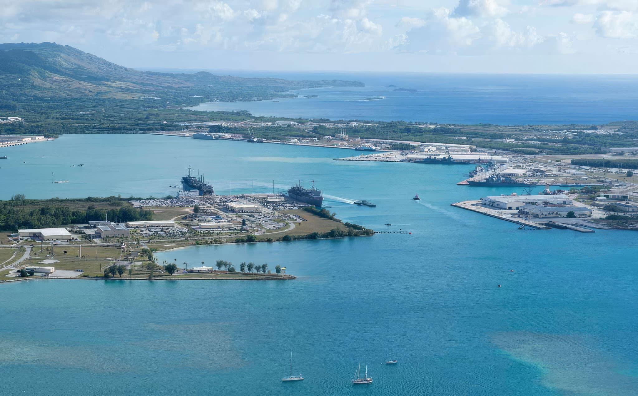
Subsea fiber optic cables carry more than 99% of international data traffic and are a core component of global communication infrastructure. Installing these systems requires precise offshore routing and controlled nearshore cable landing methods, particularly in environmentally sensitive areas. This case study documents the use of horizontal directional drilling (HDD) combined with real-time remotely operated vehicle (ROV) monitoring to support subsea cable landing in Guam. The approach enabled direct observation of HDD punch-out events, allowing for immediate verification of drill head location, reduced installation risk, and avoidance of coral reef impact.

Real-time ROV monitoring was used to observe HDD punch-out during subsea fiber optic cable landing on the West Coast of Guam, enabling direct visual confirmation of cutter head emergence. The approach allowed the drill team to verify and adjust punch-out location during active operations, maintaining all six conduits within the designated sandy seabed zone and avoiding nearby coral reef impact. Compared to conventional post-installation inspection methods, this real-time subsea monitoring reduced rework risk, eliminated delayed verification steps, and improved overall HDD installation accuracy and efficiency.
| Metric | Result |
|---|---|
| Monitoring method | Real-time subsea observation using a Deep Trekker PIVOT ROV |
| Operating depth | Over 100 feet |
| Punch-out detection | Sediment plume identified approximately 50 ft from the ROV, minutes before cutterhead emergence |
| Adjustment capability | Cutterhead retracted and repositioned during the active punch-out window |
| Verification timeline | Immediate, compared with days to weeks for post-installation diver inspection |
| Environmental outcome | No direct disturbance to the adjacent coral reef zone |
| Operational outcome | All six conduits placed within the designated sandy seabed zone, with no rework required |
This case study falls under offshore trenchless subsea cable installation engineering with real-time marine inspection systems.

Historically, the communication industry has connected continents and islands with cables laid on the sea floor. On August 5, 1858 the first successful transatlantic telegraph cable, using insulated copper, connected Europe to the United States through Valentia Island, Ireland, and Trinity Bay, Newfoundland. On August 16, 1858 Britain’s Queen Victoria sent U.S. President James Buchanan the very first message congratulating each other on their countries’ mutual success at building the very subsea cable they were communicating on.
Newspapers around the world covered this event as an important technological achievement with massive potential for future worldwide communication: news would travel faster, nations would communicate and coordinate more quickly on important world events, and business and trade would flourish.

Unfortunately, this cable failed after only three weeks from problems related to insulation damage and high voltage. While development of this subsea cable was a monumental event, following the cable's failure, it would take another eight years before another cable was laid that provided reliable communication across the Atlantic Ocean. This 1866 submarine cable worked much more reliably. Though first used for government and military purposes, this technology later allowed European immigrants to the United States to communicate with their families on the other side of the Atlantic Ocean. Over the next three decades, up to 1900, five more cables were laid across the Atlantic operating successfully. From that time, subsea copper cables have been laid across all of the world’s oceans and seas.
By the mid-to-late 20th century, fiber-optic cables began to replace copper-based subsea communication cables, dramatically increasing data capacity and efficiency. Today, submarine fiber optic cables form the backbone of the global internet, carrying over 99% of all international data traffic.

From their early days of copper telegraph cables, to today’s fiber-optic and high-voltage power transmission networks, submarine cables have played a pivotal role in global communication infrastructure. As new challenges arise, ongoing research and development has, and will continue to be vital in advancing undersea communication cable durability, efficiency, and sustainability. The future of submarine cable systems lies in innovative materials, improved monitoring capabilities, and integration with emerging underwater technologies, such as ROVs (Remotely Operated Vehicles) like the Deep Trekker PIVOT.

In the fiber optic cable industry, cables are laid on the sea bottom following a considerable ship-board effort to locate the preferred route while avoiding a myriad of obstacles: protected natural resources, oceanic trenches, and seamounts–just to name a few. It is also preferred that cables not cross over other cables.

Laying a submarine cable is a highly complex process requiring meticulous planning and state-of-the-art technology.
The installation involves:

Nearshore cable landing zones present significant engineering and environmental constraints. Coastal seabed areas often contain protected marine ecosystems, including coral reef systems monitored by regulatory and scientific organizations such as NOAA Coral Reef Conservation Program.
Construction activities in these zones are subject to sediment disturbance limits, turbidity controls, and permitting requirements defined by agencies in the United States and their Territories, such as the U.S. Environmental Protection Agency (EPA), U.S. Army Corps of Engineers (USACE), and the U.S. Fish and Wildlife Service (USFWS).

While fiber optics cables are laid on the ocean floor, they eventually must be brought ashore to a dedicated cable landing station where they are connected to the grid, providing the communication needs of the general public, industry, and military. The process of bringing these cables ashore is just as complicated a process as laying them on the ocean floor. This process includes: surveying the seabed to determine the best location, while doing the least damage to nearshore marine resources, all while protecting the cable itself.
These cables can be laid on the bottom in shallow water where ocean energy is low, but must be pinned down in some way so that they don’t move around and get damaged. Sometimes, in high energy situations, trenches are dug and the cables are buried, called “cut and cover”. Sometimes, cables are pulled through conduits that are embedded into a bulkhead for added protection.
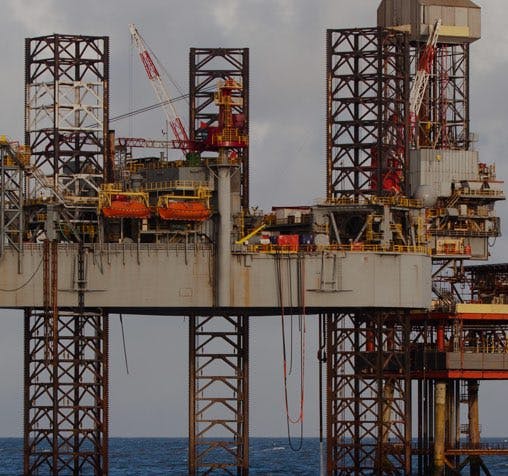
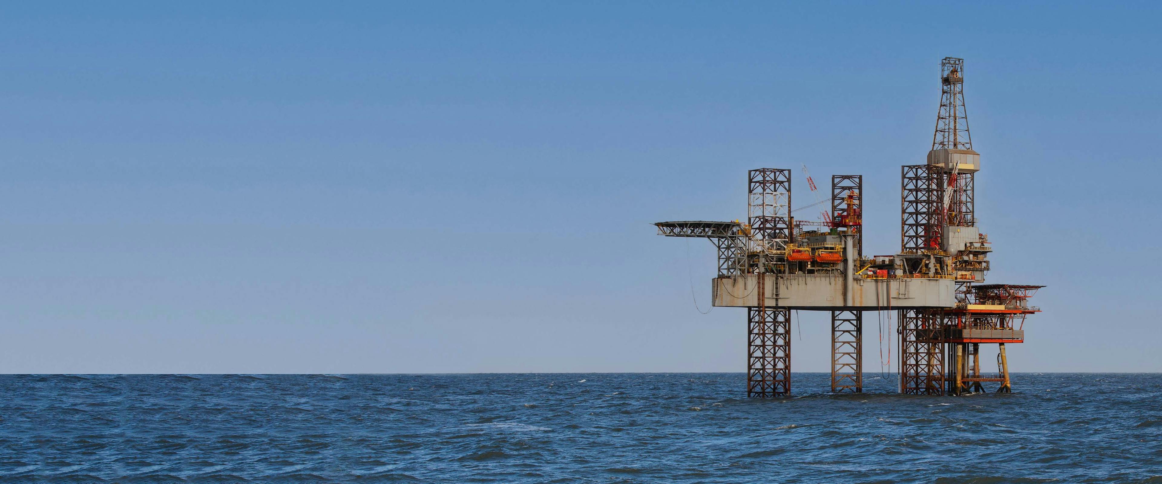
ROVs quickly detect corrosion, misalignment, and damage in subsea cables and pipelines — without costly downtime or diver risk.
Horizontal Directional Drilling (HDD) is a trenchless installation method used to route subsea cables beneath the seabed in nearshore environments. In submarine cable landing applications, HDD enables conduit installation from an onshore drill site to an offshore exit point, avoiding direct disturbance of the seabed surface. HDD systems are widely documented in trenchless engineering literature and industry standards published by the North American Society for Trenchless Technology (NASTT).

Where natural resources are important and protected, cables cannot be laid on the surface or buried in shallow trenches. In these situations, cables are installed in conduits using Horizontal Directional Drilling (HDD). This process originated in the early 1960’s, in California, pioneered by Martin Cherrington (Father of HDD) as a trenchless alternative to traditional utility installation–which required cutting through roads. The HDD methodology allowed cables to be routed beneath roads, eliminating the need for cut and cover that caused traffic holdups.
Since that time, HDD has become an important part of installing fiber optic submarine cables under the ground in rivers, lakes, and the ocean all over the world. This is the case for some fiber optic cables on the island of Guam in the Western Pacific Ocean.

Historically, cables landed on Guam were either laid on the sea bottom–protected in articulated pipe and pinned to the sea floor (surface lay)–or buried in shallow trenches (cut and cover). Both of these applications have been successful, but new environmental protection regulations often prevent such applications because the marine resources (corals) are too valuable to damage, or too difficult, or expensive to mitigate.
HDD is commonly selected for subsea cable landing in environmentally sensitive areas, including coral reef systems and protected coastal zones. By routing conduits beneath the seabed, HDD eliminates the need for surface trenching or mechanical disturbance in nearshore habitats.

Key advantages of HDD in submarine cable installation include:
However, HDD operations introduce a critical requirement: accurate control and verification of the offshore punch-out location. Deviation during drilling can result in the cutter head exiting outside the intended zone, potentially impacting protected habitats or requiring costly corrective work.
Learn how Deep Trekker's ROV successfully completed riser inspections under challenging offshore conditions, enhancing safety, efficiency, and reliability.
To avoid protected marine resources, the HDD method was used to go under them, and punch out the conduits on the sea bottom at a chosen site, seaward of the coral reef on the sandy bottom. This site was surveyed by a team of marine scientists using a remotely operated vehicle (ROV), a Deep Trekker PIVOT.

Once the site was chosen, the drill team set up their HDD drill rig on a land-based site oriented to the punch out location. One of the most important aspects of this drill operation was to make sure that the drill-head punch out was within the selected punch out location. Any deviation in the directional drilling may have caused the HDD cutter head to punch out within a protected coral zone nearby.
To make sure that the cutter head punched out in the selected site and not within protected marine resources, a team of scientists from Guam-based engineering firm, Duenas Camacho Associates, Inc. (DCA) were on location to witness the punch out using their Deep Trekker PIVOT ROV.

Real-time observation of HDD punch-out events using scuba divers or ROV video systems is rarely documented in published case studies. Most recorded examples consist of post-event inspection imagery captured after punch out has occurred, often hours to days later.
The punch-out event was monitored using a Deep Trekker PIVOT ROV deployed from a surface vessel. “We coordinated with the drill team to determine the precise day and time and identify a 30-minute punch-out window.” The DCA research team had to be on site at least an hour prior to the punch out to assure the underwater ROV was on the bottom and in position to witness the punch out event in real time.
To position the system accurately, an anchor was set on the seafloor as close as possible to the GPS coordinates of the punch-out location and connected to a surface buoy. This reference point on the ocean surface enabled the vessel operator to maintain position directly above the target site at a depth of over 100 feet.

“We flew the submersible drone to the GPS location for the punch out site and settled it on the bottom at a depth slightly deeper, and oriented shoreward looking into shallower water. In this way, we only had to scan 180 degrees of ocean floor to make sure we witnessed the punch out. And then we waited.”
The team remained on standby while monitoring updates from the drill operator regarding cutterhead progression. Upon notification that the drill head was approaching the seafloor interface, the ROV was lifted off the bottom and maneuvered laterally back and forth to scan for visual indicators of the punch-out. As this type of real-time observation had not been previously performed, pre-emergence indicators were not definitively known.
“My knowledge of the HDD process, oceanography, marine biology, and the punch out site led me to believe that the sand and loose sediments in the vicinity should be disturbed by water flowing from the HDD cutter head. So, I was looking for some kind of disturbance of sediments on the seafloor,” noted Michael J. Wilder, CEP, Marine Biologist.

After only a few minutes, there it was, a swirling mass of sediments, approximately 50 ft in the distance just off to the left. The sediment plume indicated imminent cutterhead emergence. The ROV pilot was directed to reposition toward the disturbance area for closer observation.
The ROV was maneuvered into position and held station. Within approximately one minute, the cutterhead emerged from the seafloor.

“It emerged like an alien worm with a churning set of gnarly rotating teeth spitting out a plume of sediments and an interesting globular substance that was a combination of cutting fluid (bentonite) and sand. This substance is visible in the video as it spewed out from the cutterhead and floated up into the water column.”

The team immediately relayed confirmation to the drill operator:
DRILLER ONE, DRILLER ONE
WE HAVE VISUAL ON YOUR PUNCH OUT!
WE HAVE VISUAL ON YOUR PUNCH OUT!

Based on real-time visual feedback, the drill operator requested information on cutterhead position and orientation. Using this input, the cutterhead was retracted several feet to achieve the correct exit placement.
Historically, repositioning of the conduit could not be done until days, or even weeks following a punch out, when scuba divers were deployed to inspect it, costing considerably more time and money. In this case, real-time ROV observation enabled immediate verification and correction during the operation.

The integration of ROV-based monitoring provided:
This was a huge success for DCA Inc. The approach delivered a verified punch-out on the first attempt.

This project demonstrates the application of real-time ROV inspection in HDD subsea cable landing operations, particularly in environments with strict environmental constraints and limited tolerance for positional error. By utilizing the Deep Trekker PIVOT ROV, the drill team was able to make real-time adjustments to conduit placement, reducing rework risk and improving overall installation efficiency.
Anton A. Huurdeman, The Worldwide History of Telecommunications, pp. 136–140, John Wiley & Sons, 2003 ISBN 0471205052.
Bern Dibner (1959). The Atlantic Cable. Burndy Library.
Bright, Charles (1898). Submarine telegraphs: Their History, Construction, and Working. London: C. Lockwood and son. pp. 125, 157–160, 337–339. ISBN 9781108069489. LCCN 08003683. Retrieved 2020-01-27.
Guarnieri, M. (2014). “The Conquest of the Atlantic”. IEEE Industrial Electronics Magazine. 8 (1): 53 56/67. Bibcode:2014IIEM….8a..53G. doi:10.1109/MIE.2014.2299492. S2CID 41662509.
“How submarine cables are made, laid, operated and repaired | TechTeleData – Broadband Infrastructure and Consultancy”. www.techteledata.com. Archived from the original on 2016-05-26. Retrieved 2026-03-10.
K.R. Haigh (1968). Cable ships and Submarine Cables. United States Underseas Cable Corporation.
“Milestones:TPC-1 Transpacific Cable System, 1964”. ethw.org. Engineering and Technology History WIKI. Archived from the original on 2016-09-27. Retrieved 2016-09-24.
Mohammad Woli Ullah, Mohammad Azazur Rahman, Faisal Shahriar, Zia Uddin Ahmed, Muhammad Mostafa Amir Faisal, Mohammed Jashim Uddin, Syed Zahidur Rashid, “Enlightenment of Saint Martin Island: Underwater Submarine Cable and its Reliability”, 2018 21st International Conference of Computer and Information Technology (ICCIT), pp.1-5, 2018.
“Protection of Undersea Telecommunication Cables: Issues for Congress” (PDF). www.congress.gov. Retrieved 2025-05-05.Public Domain This article incorporates text from this source, which is in the public domain.
Trenchless Drilling. 2024. Using Directional Drilling for Laying Fiber Optic Cables. Trenchless Drilling. https://trenchlessdrilling.us/using-directional-drilling-for-laying-fiber-optic-cables/
Ask us about using ROVs to inspect the risers, hull, and water tanks on your offshore platform.

March 17th, 2026
Two-day AIMS training program teaches SAR teams how to integrate sonar...
March 11th, 2026
Deep Trekker’s SPECTRA ROV integrates 3D Sonar SLAM, 4K stereo vision,...
November 3rd, 2025
At REPMUS 2025, Deep Trekker’s ROVs validated real-world mine countermeasure capabilities...